 Tweet
Tweet
By Maurizio Ramondo
After several years of hard work, my Amiga floppy drive stopped working leaving me in trouble... do I have to buy a new drive (but several disks are in bad condition too), buy a floppy emulator (nice but expensive for retro fun)...or try to use my Raspberry PI other than as xbmc player?
Disclaimer
Whatever you do with the information in these pages or on the linked pages, I am not responsible for any damage you have for using this information. The information here is provided AS-IS, and there is no warranty whatsoever!
This is a very simple and finally very cheap (5-10 eur) project: a very common chip (74LS06), a couple of resistors and diodes, a protoboard. This interface doesn't require any change to the Amiga, you have only to remove the internal floppy and put the interface and the Raspberry PI in place.

You can put the RPI so you can change/update the SD card without open the Amiga, as you see in the pictures..

The blue led on interface can be easily seen through the case holes without touching the case. As you can see, the interface needs 2 buttons I located in place of the remove disk button: the black one is the "change disk button", when pressed the next virtual floppy disk is inserted in virtual drive, and the red one is to "write to SD button", when pressed it saves all the modified disks on SD. If you push both the buttons, the interface goes in setup mode where you can choose the disk you would like to use.
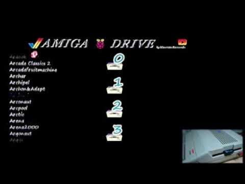
In the following video you can see how it works.
Each drive has a stack of disks chosen during setup. When the "change button" is pressed the next disk in each stack is inserted in virtual drive. As example, if I do this in setup:
drive 0:
drive 1:
After reboot Amiga will have "Monkey Island Disk1" inserted in drive 0 and "Monkey Island Disk2" inserted in drive 1. When the games asks for disk 3 or savegame disk I press the "change button" and the Raspberry PI will insert "Monkey Island Disk3" in drive 0 and "Monkey Island Disk Savegame" in drive 1. When the game asks again for disk 1 or disk 2 I only need to press again the "change button". To use is simpler than to explain...
Because the Amiga internal floppy drive connector has only 2 select line, it is not possible to have more than 2 virtual drives without modifying the Amiga, so you can only use the first and the second drive during setup (the others two will be useful with the external version of the interface).
The interface
The schematic:

Basically, for the input lines there are pull-up resistors and voltage dividers to adapt the 5V to the 3V3 of the Raspberry PI.
The SEL1 line pass through a switch so we can disable the second drive, needed if you want to attach external drives (for ripping a real floppy disk into adf file in SD).
The outputs go through the 74LS06 containing 6 inverter with open-collector outputs, needed to correctly manage the disk bus.
The RDY line is managed directly by the interface and is used to help protecting the bus when there are external drives disabling the CHNG line and the DKRD line (the other lines are managed by software).
The Raspberry PI is powered from the floppy power connection which it is enough for the model A. I tried model B, which requires more power, without any problem, but I can't recommend it because the maximum power requested in this case (700ma on certain conditions) is more than the power Amiga can provide through the connector (550ma). The interface requires Raspberry PI v.2.
These are the connectors on the Amiga we need to use, probably you would like to use the same cables used by internal floppy disk drives:
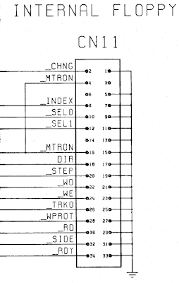
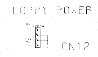
In the following image you can see the connectors of my Amiga 500 (rev.5!), I marked the pin 1 of the CN11 (it is the one near the yellow triangle) and the pin1 of the power connection (near the plastic line, 5V cable I have is brown). Be careful, the red cable (pin 4) is 12V and if you swap the cables red and brown (and there is no protection against that) you could damage Amiga and/or Raspberry PI and/or the interface.

Amiga Internal Floppy Connector and Floppy Power
These are the connections between Amiga and the interface:
Amiga RPI Drive Connections
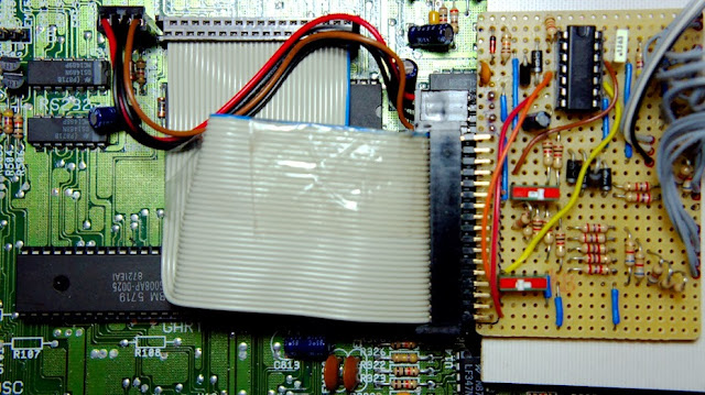
As you can see, for the interface board I didn't made a specific PCB, indeed the circuit is finally so simple I preferred to use a protoboard.

Amiga RPI Drive Interface
All the dirty work is made by the software.
The software
Here you can download the software. You have to unzip in a fat32 SD (like most of the Raspberry PI distro) and add yours adf or adz files.
I recommend to use adz, they are much shorter and they will be loaded faster. The adz files are naturally "write protected", disk modified are saved always in adf files. To make adz files you just need to gzip the adf files with some free utility like 7-zip and change the extension to adz, or you could use powershell command: gzip filename.
That's all. The emulation is "complete" so Amiga will save the changes you made on the disks: the changes will stay only in memory until you press the "write to sd button". You can see the disks modified (which probably need to be saved on SD) during setup, they will have an asterisk before the name. Then if the disks are modified, they will be write back to sd making or overwriting the adf files, unless the files are marked as "read-only" on SD.
You can easily rip your disks just using an external drive and XCopy (I put inside the zip file) or you can do the opposite, you can create an Amiga floppy disk from an adf file, just remember to disable the second drive on interface before attaching the external drive.

In the video you can see me ripping my old Workbench disk.
Interface details
This interface don't use Linux kernel, but is bare metal, so everything it is done from scratch starting without any S.O. support. All the code is in kernel.img in only 240kb, it holds also the Amiga setup software (and sounds and graphics). So it is only needed 7 second to power up the system and start the emulation. This choice was because the floppy disk interface needs real time response and Linux can't manage that without adding external hardware.
Since this interface manages more than 1 drive (it can manage 4) and it is supposed the disk bus is shared eventually with external drives, several signals (as CHNG) need to be managed by software in real time (answers not after than 400 ns) and only a bare metal system, with optimized code, can manage that.
You can find more info on timings here (example for Amiga floppy) and here (for generic PC floppy).
During SD operations like read or write an adf/adz disk image, the system can't manage the bus requests. In this case the full emulation is stopped and the system appears like without disks inserted (all the disks will be 'ejected'): in this way the hardware can directly manage the requests without generate errors or blocks. In this way the RPI is free to do something else. After these operations the emulation will start again and all the disks will be re-inserted in drives.
In order to manage the DKRD line (disk read) and have a full stream of data with exact timing (2us per cell) sent without any interruptions,holes or delays, the software uses the SPI interface in continuous mode: all the MFM data goes through the SDO pin while other SPI pins are not used and they are configured and treated as standard GPIO.
In order to have a better shape for the DKRD line, the signal should stay low for less than 2 us (400ns should be good) so the signal was 'reshaped' by the resistor R15, the capacitor C3 and the diode D6, improving the compatibility with the Amiga software (really only few games are sensible to this timing).
For the data in input, the DKWD line, indeed it was not possible to use SDI because without a clock or a PLL, errors will appear soon. The approach in this case was to take the times between the 0 cells (on the falling edge) and use these to obtain the data stream.
So if between 2 zeros there are 4 us, the system recognizes a '10' sequence (the line is inverted), if there are 6 us the system recognizes a '100' sequence and if there are 8 us the system recognize '1000', as it's the MFM coding.
To know more about MFM coding anyway and other useful stuff here there are lots of info.
I hope you enjoy again Amiga as I did!
This is the software
Amiga RPI Drive.zip
Feel free to use and distribute.
Feel free to leave comments/suggestions.
Special thanks for the FatFS module to http://elm-chan.org/fsw/ff/00index_e.html
After several years of hard work, my Amiga floppy drive stopped working leaving me in trouble... do I have to buy a new drive (but several disks are in bad condition too), buy a floppy emulator (nice but expensive for retro fun)...or try to use my Raspberry PI other than as xbmc player?
Disclaimer
Whatever you do with the information in these pages or on the linked pages, I am not responsible for any damage you have for using this information. The information here is provided AS-IS, and there is no warranty whatsoever!
This is a very simple and finally very cheap (5-10 eur) project: a very common chip (74LS06), a couple of resistors and diodes, a protoboard. This interface doesn't require any change to the Amiga, you have only to remove the internal floppy and put the interface and the Raspberry PI in place.

You can put the RPI so you can change/update the SD card without open the Amiga, as you see in the pictures..

The blue led on interface can be easily seen through the case holes without touching the case. As you can see, the interface needs 2 buttons I located in place of the remove disk button: the black one is the "change disk button", when pressed the next virtual floppy disk is inserted in virtual drive, and the red one is to "write to SD button", when pressed it saves all the modified disks on SD. If you push both the buttons, the interface goes in setup mode where you can choose the disk you would like to use.
In the following video you can see how it works.
- at power up the setup program will start automatically
- choice all the disks you would like to use
- start playing games; if you want to use another disk, push the "change button"
- when you want to play another game just press both the button and reset the Amiga, the system will go in the setup mode
Each drive has a stack of disks chosen during setup. When the "change button" is pressed the next disk in each stack is inserted in virtual drive. As example, if I do this in setup:
drive 0:
- Monkey Island Disk1
- Monkey Island Disk3
drive 1:
- Monkey Island Disk2
- Monkey Island Disk Savegame
After reboot Amiga will have "Monkey Island Disk1" inserted in drive 0 and "Monkey Island Disk2" inserted in drive 1. When the games asks for disk 3 or savegame disk I press the "change button" and the Raspberry PI will insert "Monkey Island Disk3" in drive 0 and "Monkey Island Disk Savegame" in drive 1. When the game asks again for disk 1 or disk 2 I only need to press again the "change button". To use is simpler than to explain...
Because the Amiga internal floppy drive connector has only 2 select line, it is not possible to have more than 2 virtual drives without modifying the Amiga, so you can only use the first and the second drive during setup (the others two will be useful with the external version of the interface).
The interface
The schematic:

Code:
     Partlist

     IC1                  74LS06
     C1                   10uF
     C2                   100nF
     C3                   220pf
     D1-D5/D7             SB140 (*6)
     D6                   1N4148
     R8/R14/R16/R26/R27   4k7 (*5)
     R15                  10k
     R1-R7                1k (*7)
     R9-R13/R17/R18       2k7 (*7)
     R19-R25              6k8 (*7)
     R28                  330
     LED1                 3mm 2.7V 2ma
     S1                   switch
     JP1                  Amiga Floppy Power   1X4
     JP2                  Amiga Internal Drive 2X17
     JP3                  Raspberry PI         2X13
The SEL1 line pass through a switch so we can disable the second drive, needed if you want to attach external drives (for ripping a real floppy disk into adf file in SD).
The outputs go through the 74LS06 containing 6 inverter with open-collector outputs, needed to correctly manage the disk bus.
The RDY line is managed directly by the interface and is used to help protecting the bus when there are external drives disabling the CHNG line and the DKRD line (the other lines are managed by software).
The Raspberry PI is powered from the floppy power connection which it is enough for the model A. I tried model B, which requires more power, without any problem, but I can't recommend it because the maximum power requested in this case (700ma on certain conditions) is more than the power Amiga can provide through the connector (550ma). The interface requires Raspberry PI v.2.
These are the connectors on the Amiga we need to use, probably you would like to use the same cables used by internal floppy disk drives:


In the following image you can see the connectors of my Amiga 500 (rev.5!), I marked the pin 1 of the CN11 (it is the one near the yellow triangle) and the pin1 of the power connection (near the plastic line, 5V cable I have is brown). Be careful, the red cable (pin 4) is 12V and if you swap the cables red and brown (and there is no protection against that) you could damage Amiga and/or Raspberry PI and/or the interface.

Amiga Internal Floppy Connector and Floppy Power
These are the connections between Amiga and the interface:

Amiga RPI Drive Connections
As you can see, for the interface board I didn't made a specific PCB, indeed the circuit is finally so simple I preferred to use a protoboard.

Amiga RPI Drive Interface
All the dirty work is made by the software.
The software
Here you can download the software. You have to unzip in a fat32 SD (like most of the Raspberry PI distro) and add yours adf or adz files.
I recommend to use adz, they are much shorter and they will be loaded faster. The adz files are naturally "write protected", disk modified are saved always in adf files. To make adz files you just need to gzip the adf files with some free utility like 7-zip and change the extension to adz, or you could use powershell command: gzip filename.
That's all. The emulation is "complete" so Amiga will save the changes you made on the disks: the changes will stay only in memory until you press the "write to sd button". You can see the disks modified (which probably need to be saved on SD) during setup, they will have an asterisk before the name. Then if the disks are modified, they will be write back to sd making or overwriting the adf files, unless the files are marked as "read-only" on SD.
You can easily rip your disks just using an external drive and XCopy (I put inside the zip file) or you can do the opposite, you can create an Amiga floppy disk from an adf file, just remember to disable the second drive on interface before attaching the external drive.
In the video you can see me ripping my old Workbench disk.
Interface details
This interface don't use Linux kernel, but is bare metal, so everything it is done from scratch starting without any S.O. support. All the code is in kernel.img in only 240kb, it holds also the Amiga setup software (and sounds and graphics). So it is only needed 7 second to power up the system and start the emulation. This choice was because the floppy disk interface needs real time response and Linux can't manage that without adding external hardware.
Since this interface manages more than 1 drive (it can manage 4) and it is supposed the disk bus is shared eventually with external drives, several signals (as CHNG) need to be managed by software in real time (answers not after than 400 ns) and only a bare metal system, with optimized code, can manage that.
You can find more info on timings here (example for Amiga floppy) and here (for generic PC floppy).
During SD operations like read or write an adf/adz disk image, the system can't manage the bus requests. In this case the full emulation is stopped and the system appears like without disks inserted (all the disks will be 'ejected'): in this way the hardware can directly manage the requests without generate errors or blocks. In this way the RPI is free to do something else. After these operations the emulation will start again and all the disks will be re-inserted in drives.
In order to manage the DKRD line (disk read) and have a full stream of data with exact timing (2us per cell) sent without any interruptions,holes or delays, the software uses the SPI interface in continuous mode: all the MFM data goes through the SDO pin while other SPI pins are not used and they are configured and treated as standard GPIO.
In order to have a better shape for the DKRD line, the signal should stay low for less than 2 us (400ns should be good) so the signal was 'reshaped' by the resistor R15, the capacitor C3 and the diode D6, improving the compatibility with the Amiga software (really only few games are sensible to this timing).
For the data in input, the DKWD line, indeed it was not possible to use SDI because without a clock or a PLL, errors will appear soon. The approach in this case was to take the times between the 0 cells (on the falling edge) and use these to obtain the data stream.
So if between 2 zeros there are 4 us, the system recognizes a '10' sequence (the line is inverted), if there are 6 us the system recognizes a '100' sequence and if there are 8 us the system recognize '1000', as it's the MFM coding.
To know more about MFM coding anyway and other useful stuff here there are lots of info.
I hope you enjoy again Amiga as I did!
This is the software
Amiga RPI Drive.zip
Feel free to use and distribute.
Feel free to leave comments/suggestions.
Special thanks for the FatFS module to http://elm-chan.org/fsw/ff/00index_e.html